
Configuring a Wireless LAN Connection
The Cisco 850 and Cisco 870 series routers support a secure, affordable,
and easy-to-use wireless LAN solution that combines mobility and
flexibility with the enterprise-class features required by networking
professionals. With a management system based on Cisco IOS software, the
Cisco routers act as access points, and are Wi-Fi certified, IEEE
802.11a/b/g-compliant wireless LAN transceivers.
You can configure and monitor the routers using the command-line
interface (CLI), the browser-based management system, or Simple Network
Management Protocol (SNMP). This chapter describes how to configure the
router using the CLI. Use the interface dot11radio global configuration CLI command to place the device into radio configuration mode.
See the Cisco Access Router Wireless Configuration Guide for more detailed information about configuring these Cisco routers in a wireless LAN application.
Figure 9-1 shows a wireless network deployment.
Figure 9-1 Wireless Connection to the Cisco Router
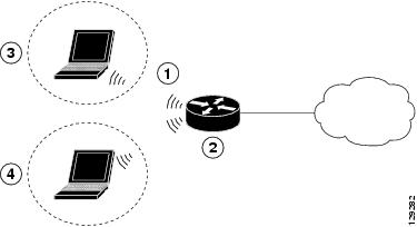
1
|
Wireless LAN (with multiple networked devices)
|
2
|
Cisco 850 or Cisco 870 series access router connected to the Internet
|
3
|
VLAN 1
|
4
|
VLAN 2
|
In the configuration example that follows, a remote user is accessing
the Cisco 850 or Cisco 870 series access router using a wireless
connection. Each remote user has his own VLAN.
Configuration Tasks
Perform the following tasks to configure this network scenario:
A configuration example showing the results of these configuration tasks is provided in the "Configuration Example" section.

Note  The
procedures in this chapter assume that you have already configured
basic router features as well as PPPoE or PPPoA with NAT. If you have
not performed these configurations tasks, see Chapter 1 "Basic Router Configuration," Chapter 3 "Configuring PPP over Ethernet with NAT," and Chapter 4 "Configuring PPP over ATM with NAT," as appropriate for your router. You may have also configured DHCP, VLANs, and secure tunnels.
The
procedures in this chapter assume that you have already configured
basic router features as well as PPPoE or PPPoA with NAT. If you have
not performed these configurations tasks, see Chapter 1 "Basic Router Configuration," Chapter 3 "Configuring PPP over Ethernet with NAT," and Chapter 4 "Configuring PPP over ATM with NAT," as appropriate for your router. You may have also configured DHCP, VLANs, and secure tunnels.
Configure the Root Radio Station
Perform these steps to create and configure the root radio station for
your wireless LAN, beginning in global configuration mode:
Command
|
Purpose
|
|
|---|---|---|
Step 1
|
interface name number
Example:
Router(config)# interface dot11radio 0
Router(config-if)# |
Enters interface configuration mode for the radio interface.
|
Step 2
|
broadcast-key [vlan vlan-id] change seconds
Example:
Router(config-if)# broadcast-key vlan 1
change 45
Router(config-if)# |
Specifies the time interval, in seconds, between rotations of the broadcast encryption key used for clients.
Note
Note
See the Cisco IOS Commands for Access Points and Bridges for more details.
|
Step 3
|
encryption method algorithm key
Example:
Router(config-if)# encryption vlan 1 mode
ciphers tkip
Router(config-if)# |
Specifies the encryption method, algorithm, and key used to access the wireless interface.
The example uses the VLAN with optional encryption method of data ciphers.
|
Step 4
|
ssid name
Example:
Router(config-if)# ssid cisco Router(config-if-ssid)# |
Creates a Service Set ID (SSID), the public name of a wireless network.
Note
|
Step 5
|
vlan number
Example:
Router(config-if-ssid)# vlan 1 Router(config-if-ssid)# |
Binds the SSID with a VLAN.
|
Step 6
|
authentication type
Example:
Router(config-if-ssid)# authentication open Router(config-if-ssid)# authentication network-eap eap_methods Router(config-if-ssid)# authentication key-management wpa |
Sets the permitted authentication methods for a user attempting access to the wireless LAN.
More than one method can be specified, as shown in the example.
|
Step 7
|
exit
Example:
Router(config-if-ssid)# exit Router(config-if)# |
Exits SSID configuration mode, and enters interface configuration mode for the radio interface.
|
Step 8
|
speed rate
Example:
Router(config-if)# basic-1.0 basic-2.0
basic-5.5 6.0 9.0 basic-11.0 12.0 18.0 24.0
36.0 48.0 54.0
Router(config-if)# |
(Optional) Specifies the required and allowed rates, in Mbps, for traffic over the wireless connection.
|
Step 9
|
rts [retries | threshold]
Example:
Router(config-if)# rts threshold 2312 Router(config-if)# |
(Optional) Specifies the Request to Send (RTS) threshold or the number
of times to send a request before determining the wireless LAN is
unreachable.
|
Step 10
|
power [client | local] [cck [number | maximum] | ofdm [number | maximum]]
Example:
Router(config-if)# power local cck 50 Router(config-if)# power local ofdm 30 Router(config-if)# |
(Optional) Specifies the radio transmitter power level.
See the Cisco Access Router Wireless Configuration Guide for available power level values.
|
Step 11
|
channel [number | least-congested]
Example:
Router(config-if)# channel 2462 Router(config-if)# |
(Optional) Specifies the channel on which communication occurs.
See the Cisco Access Router Wireless Configuration Guide for available channel numbers.
|
Step 12
|
station-role [repeater | root]
Example:
Router(config-if)# station-role root Router(config-if)# |
(Optional) Specifies the role of this radio interface.
You must specify at least one root interface.
|
Step 13
|
exit
Example:
Router(config-if)# exit Router(config)# |
Exits interface configuration mode, and enters global configuration mode.
|
Configure Bridging on VLANs
Perform these steps to configure integrated routing and bridging on VLANs, beginning in global configuration mode:
Configure Radio Station Subinterfaces
Perform these steps to configure subinterfaces for each root station, beginning in global configuration mode:
Repeat these steps to configure more subinterfaces, as needed.
Configuration Example
The following configuration example shows a portion of the configuration
file for the wireless LAN scenario described in the preceding sections.
!
bridge irb
!
interface Dot11Radio0
no ip address
!
broadcast-key vlan 1 change 45
!
!
encryption vlan 1 mode ciphers tkip
!
ssid cisco
vlan 1
authentication open
wpa-psk ascii 0 cisco123
authentication key-management wpa
!
ssid ciscowep
vlan 2
authentication open
!
ssid ciscowpa
vlan 3
authentication open
!
speed basic-1.0 basic-2.0 basic-5.5 6.0 9.0 basic-11.0 12.0 18.0 24.0 36.0 48.0 54.0
rts threshold 2312
power local cck 50
power local ofdm 30
channel 2462
station-role root
!
interface Dot11Radio0.1
description Cisco Open
encapsulation dot1Q 1 native
no cdp enable
bridge-group 1
bridge-group 1 subscriber-loop-control
bridge-group 1 spanning-disabled
bridge-group 1 block-unknown-source
no bridge-group 1 source-learning
no bridge-group 1 unicast-flooding
!
interface Dot11Radio0.2
encapsulation dot1Q 2
bridge-group 2
bridge-group 2 subscriber-loop-control
bridge-group 2 spanning-disabled
bridge-group 2 block-unknown-source
no bridge-group 2 source-learning
no bridge-group 2 unicast-flooding
!
interface Dot11Radio0.3
encapsulation dot1Q 3
bridge-group 3
bridge-group 3 subscriber-loop-control
bridge-group 3 spanning-disabled
bridge-group 3 block-unknown-source
no bridge-group 3 source-learning
no bridge-group 3 unicast-flooding
!
interface Vlan1
no ip address
bridge-group 1
bridge-group 1 spanning-disabled
!
interface Vlan2
no ip address
bridge-group 2
bridge-group 2 spanning-disabled
!
interface Vlan3
no ip address
bridge-group 3
bridge-group 3 spanning-disabled
!
interface BVI1
ip address 10.0.1.1 255.255.255.0
!
interface BVI2
ip address 10.0.2.1 255.255.255.0
!
interface BVI3
ip address 10.0.3.1 255.255.255.0
!
 Subscribe to email feed


